Electric Power Quality and Dynamic Voltage Regulator
Electric power quality is a term which importance is increasing day by day. The increasing demand for electrical energy, the change in load characteristics, and the penetration of renewable energy sources such as solar and wind power generation facilities into the electricity grid have revealed the importance of the concept of electrical power quality. Electrical power quality can be defined as a set of electrical parameters and limits that enable end-user loads or equipment connected to the electrical grid to operate as desired without a significant loss of performance and operating-life. Electrical power quality problems can be defined as power problems caused by voltage, current, and frequency changes that cause failure or malfunction of end-user loads or equipment connected to the electrical grid.
The most common power quality problems encountered in electrical grids are voltage sag, voltage swell, overvoltage, under-voltage, and voltage unbalance. These power quality events cause the trip of loads, the failure of the equipment, and the interruption of the industrial process resulting in serious economic losses. Dynamic voltage regulator (DVR) provides the most effective solution for these voltage quality problems. DVR is a power electronics-based power quality compensation system that is connected in series with the grid. DVR provides effective protection by preventing the voltage quality events occurring in the grid from being seen on the load side with its high-performance voltage compensation ability.
Basic Working Principle
The main purpose of DVR is to provide voltage quality on the load side by detecting and compensating power quality events occurring in the grid voltage in less than a half-cycle period. The block diagram showing the basic working principle of DVR is given in Figure 1. DVR basically consists of a control system and a power circuit. The control system of DVR continuously monitors the grid voltage, detects the power quality events occurring in the voltage less than a half cycle period with the help of the control and detection methods, and generates the control signals required for the compensation. The power circuit of the DVR generates the compensation voltage and inject it into the grid in series to prevent voltage quality problems on the load side. Therefore, it ensures that the loads are protected from voltage quality problems occurring in the grid.
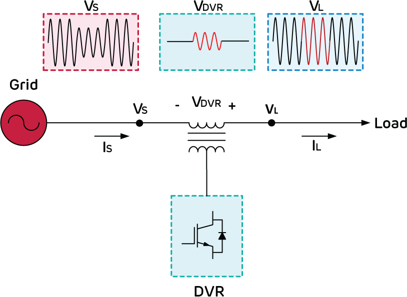
Figure 1 – DVR Working Principle
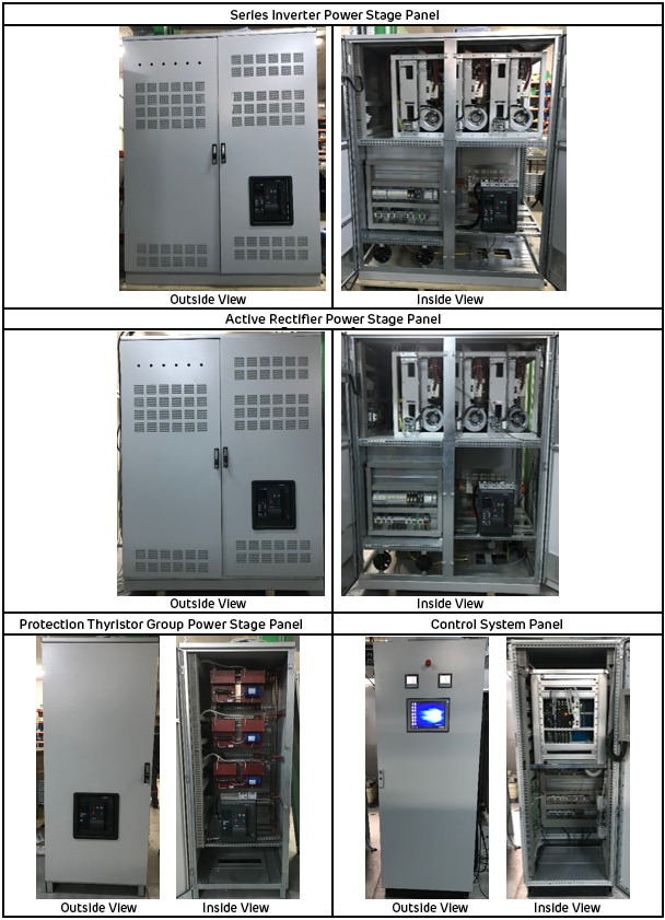
Power Stage Topology
The single line representation of the power stage of the DVR is given in Figure 2. The DVR power stage consists of active rectifier power and serial inverter power stages connected back to back over the DC capacitor bank.
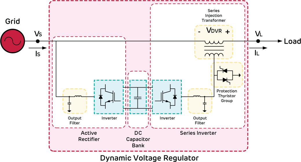
Figure 2 – DVR power stage single line circuit diagram
An active rectifier is an IGBT based rectifier type controlled by PWM signals. It has much lower current harmonic distortion (THD:<3%) than conventional diode/thyristor rectifiers. The main function of the active rectifier is to provide the constant DC voltage required for the compensation according to the switching signals from the control system. The power stage of the active rectifier consists of the inverter, the DC link capacitor bank, and the output filter. According to the switching signals sent by the inverter control system, it controls the flow of the necessary active power from the grid to provide the required fixed DC link voltage. The output filter is used to filter the switching harmonics generated by the active rectifier inverter.
The series inverter power stage consists of the inverter, output filter, protection thyristor group, and injection transformer. The inverter generates the voltage required for compensation according to the switching signals generated by the control system. The output filter is used to filter the switching harmonics generated by the series inverter, as in the active rectifier filter. The protection thyristor group consists of thyristors connected anti-parallel to each other for each phase. The protection thyristor group is activated in case of an error in the grid or DVR, ensuring the disconnection of the series inverter power stage and protection of the system. The injection transformer, on the other hand, ensures that the compensation voltage produced by the inverter is injected in series to the grid and isolation between the grid and the DVR.
The DC-link capacitor bank is used to store the energy required for the DVR to meet the expected compensation requirements within the period until the active rectifier controller reacts at the moment of compensation.